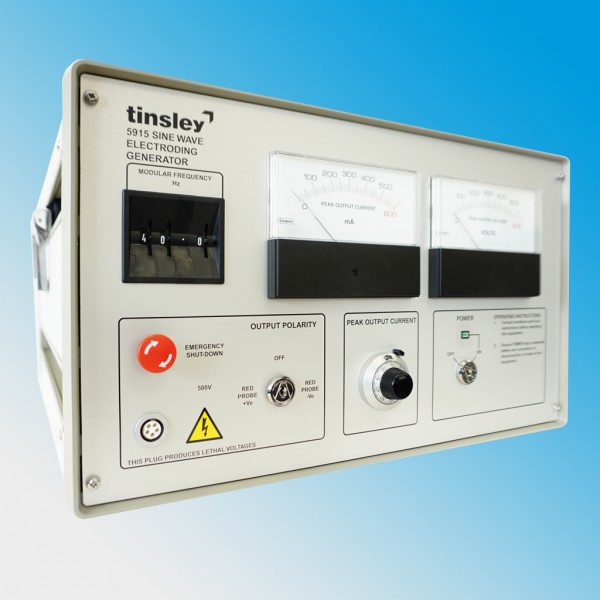
Electroding Generator 5915
The Tinsley Electroding Generator, type 5915, has been developed with British Telecom to locate Submarine Telephone Cables. The method employed is the well established electroding technique. The unit is self-contained, desk top mounting, enabling tests to be carried out without the power feed connected to the cable under test.
For more information about this product contact Tinsley
The 5915 Tinsley Electroding Generator is intended as an aid to cable repair ships in locating and identifying telephone cables. The Electroding Generator energises the Submarine Cable with a low frequency sine wave signal of up to 500mA at 500 Volts peak to peak. The Electroding Generator is located in the terminal station normally nearest to the fault area and connected to the cable under test by means of two safety probes built-in the instrument.
Principle of Operation
The Electroding Generator is a low frequency oscillator with a sine wave output capable of delivering up to 500mA at 500 Volts peak to peak at any frequency from 5Hz to 99.9Hz. The frequency is selected by digital thumbwheel switches, peak current is set via a front panel rotary control. The Current and Voltage levels are clearly displayed on Front Panel Precision Analogue Meters.
The current waveform is controlled to be sinusoidal. The test current has a DC bias to improve the sensitivity detection over longer distance. The test current can be applied in either the forward direction only or in the reverse or forward bias, as required. Longer cable can normally be electroded by energising in the reverse direction. A crystal controlled oscillator ensures that the frequency does not drift while testing is in progress.
Output connections are made by permanently connected probes, which are fully shrouded. A safety circuit disables the Generator output whilst the probes are being applied to the cable under test. A special compartment on the rear of the instrument is provided for stowing the output probes when not in use.
A frequency monitor point (square wave at signal frequency) is provided on the rear on the instrument. Output level is TTL compatible.
Watch our new movie to see the features and benefits of our 5915 Sine Wave Electroding Generator.

Specifications
See the table below for a run-down of this product's specifications.
Output | Continuously adjustable current regulated d.c. - sine wave modulated |
Current Range | Minimum 75mA modulated at ± 25mA |
Current Regulation | < 5% |
Current Control | Continuously adjustable by 10-turn potentiometer |
Mains Switching | Key operated. The key is removable only in the off position |
Voltage | 500V peak max |
Polarity | Output polarity is selected by means of a 3 position key switch (Positive, Off, Negative) |
Monitoring | Both current and voltage are continuously monitored by individual front panel meters of accuracy 3% F.S.D |
Modulation Frequency | |
Range | 5Hz to 99.9Hz, selected in 0.1Hz steps. |
Accuracy | ± 0.01Hz |
Stability | 0.03% Long term (12hr). 0.003% Short term (10min). |
Output distortion | THD 5% |
Controls | Adjustable by thumbwheel edge switches. |
Power requirements |
105V to 125V or 210V to 250V; 50Hz to 60Hz, (selected via rear panel). |
Weight and dimensions | |
Size | 300H x 512D x 470W (mm) approx. |
Weight | 26.5kg approx |
